Wednesday 22 April 2020

GTW Automobile Car Part 2

Continuing on from part 1, I finished the under frame by using 0.010" Tichy wire for the 3/4" diameter brake rods of the prototype.  Most 40 and 50 foot cars used either 3/4" or 7/8" diameter steel rod for the brake rods depending on tonnage rating.  The levers are from Yarmouth Model Works.  A piece of 40 links per inch chain connects the hand brake rod to the cylinder lever.


The model as provided doesn't have an attachment for the running board laterals.  They just float in mid air.  To rectify this add short pieces of 0.010" x 0.030" styrene strip, bent into an 'L' and glued to the underside of the lateral and to the edge of the roof.  I added a rivet to each which I harvested from  an Athearn boxcar.  


To detail the ends, drill and mount wire grabs and 1" nut bolt washer parts above them.  The prototype bracket grab can be simulated with a Kadee grab by cutting one end off and mounting it 90 degrees on the inboard end.  A small drop of CA will re attach the two halves of the grab together.  


The next improvement is to correct the side sill.  Remove 0.5" from the lower right hand side of the sill reinforcement.  Then cut it on a 45 degree angle.  Follow this by extending the left end of the sill reinforcement by 0.5" with a piece of 0.040" by 0.080" styrene.  Taper the end of it by 45 degrees also.


The running board end supports are fairly crude, so I created new ones from 0.010" x 0.030" styrene and a couple of harvested rivets.  Next I installed an etched brake step and supports made from 0.010" x 0.030" styrene and harvested rivets again.

I carved off the brake housing and installed an Ajax uint from Tichy along with a Kadee brake wheel.  Lastly the retainer valve pipe has been replaced with 0.008" wire to represent the 3/8" NPT pipe used on the prototype.


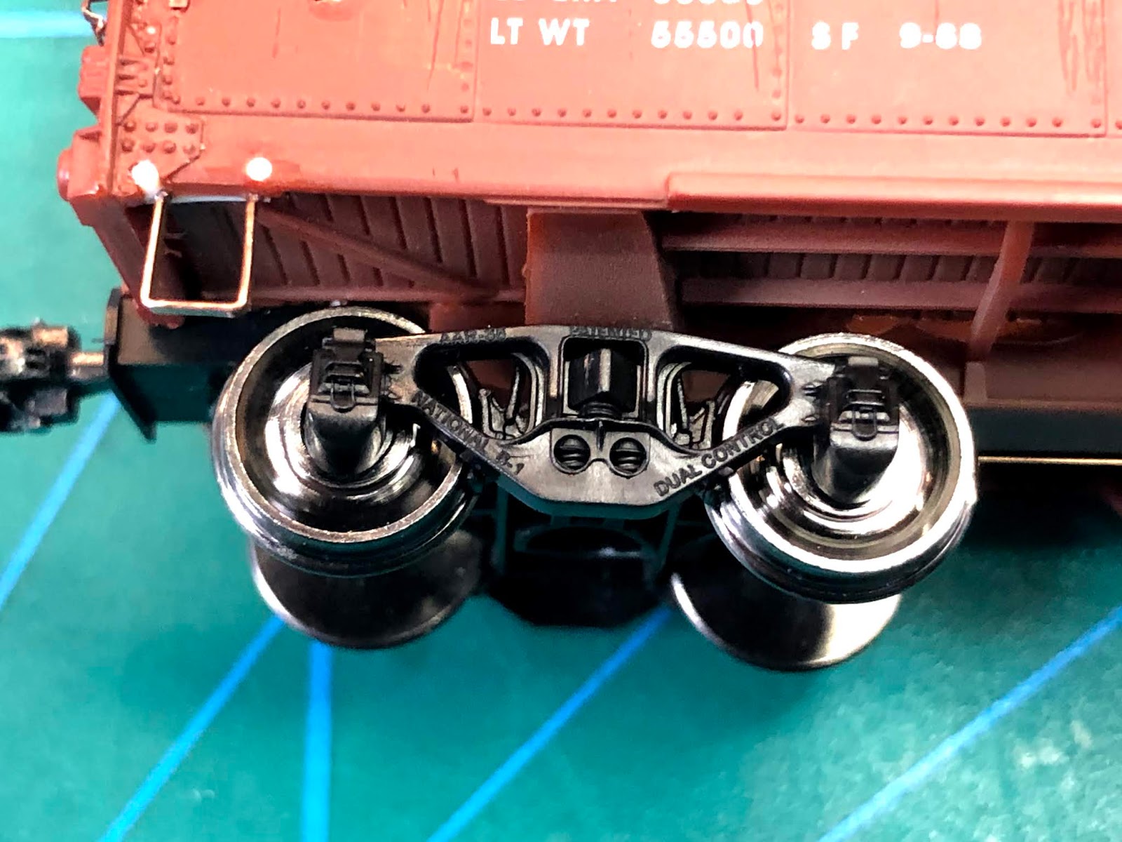
The prototype has bottom mount sill steps.  Installing A line sill steps is a simple upgrade that not only matches those used on the prototype, but they are much more durable.  The left end uses a straight step while the right end uses a single angle step.  The second view also shows the National B1 truck.  Note of caution, the sides are very thin so add a piece of styrene behind the sill to thicken it so you can drill without breaking through.


The last easy upgrade is to add the upper door bits.  In the middle add two pieces of styrene to make up an 'L' shape.  First glue a piece of  0.010" x 0.040" flat against the track.  Then add a pice of 0.020" x 0.020" along the bottom edge of the first piece.  Finish up by adding four small pieces of 0.010" x 0.040" to represent the the small tabs at the top of each door.


I added tack boards and route card holders from my National Scale Parts line.  The kit comes with two board versions, but these cars had three board versions.  I still need to add brake hoses and cut levers.  At this point a bit of touch up paint, either brushed or sprayed on and you would end up with a fairly creditable representation of the prototype.  Further improving the car requires fixing the steel panels on the side of the car body.

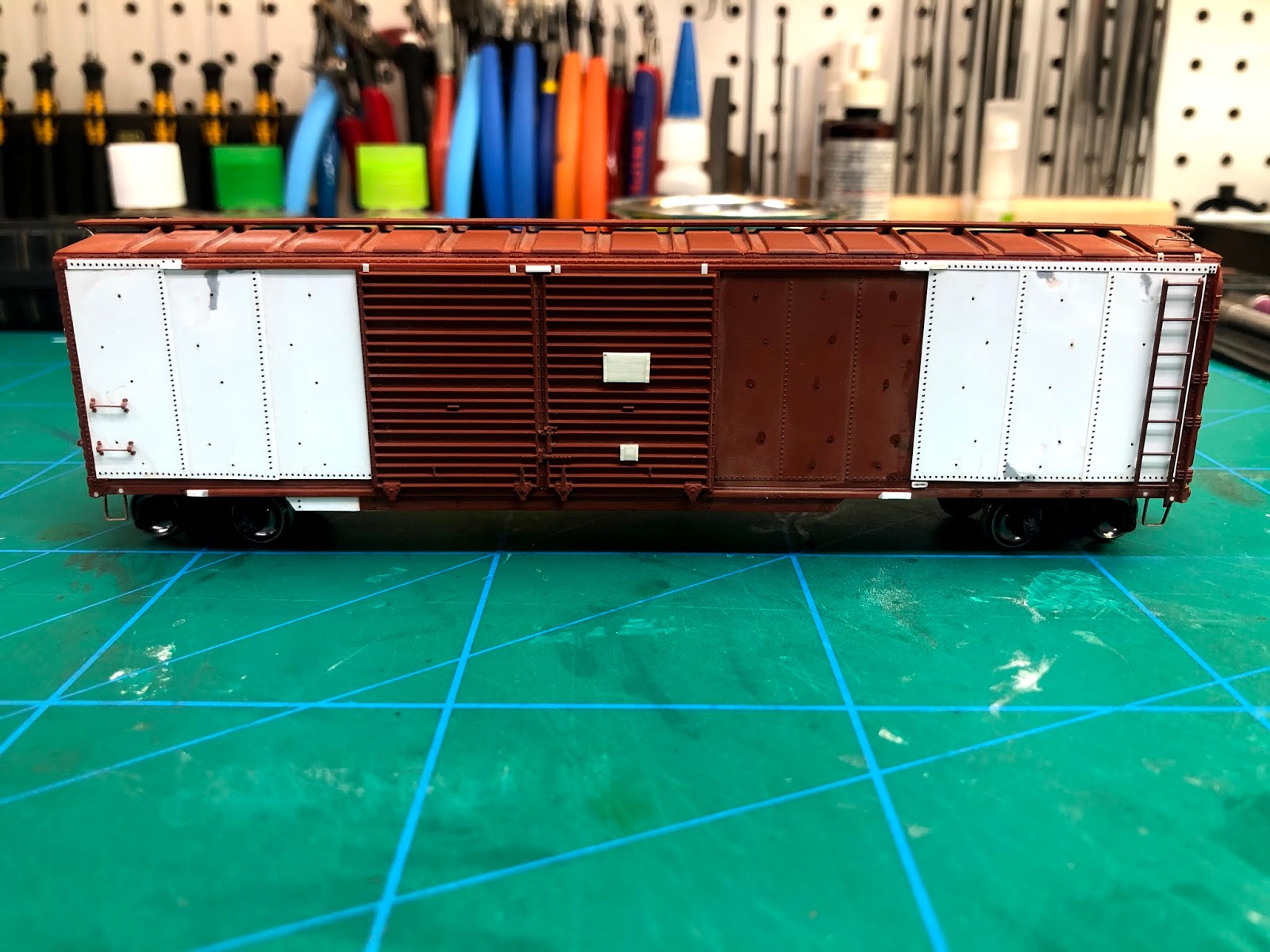
I decided that this could be easily done with 0.005" styrene and both harvested rivets and Archer rivets.  The Proto 2000 car has 4 panels to the right of the door and 7 to the right.  The prototype has three to the left of the door and six to the right.  The ones on the right use two different widths also.  To begin the conversion use a chisel blade and remove all the rivets where the new panels go.  Then sand the panel seams.  Not every last bit needs to be removed.  Then cut 0.005" thick styrene sheet into 0.600" strips and cut using a chopper to length.  Apply the panels working from the inside of the car to the ends,  maintaining the correct overlap.  I word of caution on glue.  Use very little and a really small brush.  I prefer Tamiya Extra Fine " Quick Set". It is the least hot of all the styrene glues I have tried.  It flashes off very quickly and doesn't smell as bad as MEK.  Even with caution I still had a couple of glue sink marks.  These were corrected with a bit of filler and wet sanding. The three panels to the right of the door were not replaced.  I sand blasted the car before starting so the glue would not have to work though the paint.


I added door stops from my National Scale Car parts line, to replace those carved off in the panel replacement.  Archers rivets are used on the panels edges and bottoms.  Harvested rivets are used for the loading rack rivets in the middle of the panels and to detail the under frame attachment to the side sill.  I had a spare set of ladders that I used for the sides as the originals were bent.  The last detail is to add the Kadee bracket grabs to the left ends of the sides.


I need to source some decals for this car.  A set exists for a 40' GTW Steel Car, but I may have to pull from a few sets to make up some of the data for this 50 footer.

I will show the final car in Part 3.

Saturday 18 April 2020

GTW Automobile Car Part 1

 The GTW Western rostered some of the earliest examples of 50' Automobile cars built similar to the to the 1937 40' AAR Standard boxcars.

 Cars 591000-591199 were built by Pullman Standard in 1937,  had End doors and square corner post 5-5 dreadnaught ends on the B end.  They rode on AAR cast side frame, spring plank-less trucks. The side sills were continuous and had a large reinforcement member under the doors, which were of the Youngstown type.  The roofs were Murphy raised panel and had wood running boards.

 Cars in the following series 591200-591399 built 1941 were similar except they had round corner 5-5 Dreadnaught ends on the B end. They rode on National B1 trucks.

 The Proto 2000 50' auto car with end doors are almost spot on for this second series of cars. Although a few changes will make for a more accurate car.

 If you're a modeller thinking about dipping your toe into the prototype modelling pond - building one of these kits would make for a great first project.  The body requires no major surgery and only minor changes are required to produce an accurate representation of the prototype.  Kits are available prepainted and lettered.  Only basic hobby tools are required for the work.

Here is a picture of the prototype car taken in 1969 by Steve Rush.  The original can be found on Rail Picture Archives in colour.


 By 1969 the car has undergone some changes.  The trucks have been changed out, incidentally to the type of truck the previous series rode on.  The sides have been patched to reinforce the car body around the bottom of the door openings and an ACI tracking label has been fitted.  Evidence of paint touch up can also be spotted on the reinforcement member under the doors. Since I model 1955, I will not be making any of these changes.  Other than these minor repairs this car has undergone little change since it was built in 1941.

 My car was purchased used and was already assembled.  I decided to remove most of the detail parts.   They were half  broken and not fitted correctly. I left the ladders on for now, but they are not straight and I may upgrade them if I can't straighten them up.

 I started by gluing the doors on straight and centered in the opening.  The kit comes with a plug that goes between the doors at the top, don't install this part as it is much too large and is easy to upgrade.  Next I installed couplers and Athearn National B1 trucks.  These trucks are also available from Walthers and Kadee. Save the kit trucks for another project, or if your modelling 1969 go ahead and use them!


 Next, I plugged all the holes on the sides and roof where the detail parts were removed.  To do this, drill out the holes with a 0.030" drill bit and then glue in short lengths of 0.030" styrene rod.  When dry, trim off with nippers and sand or chisel smooth with a knife blade.  Details that were removed are as follows: all grabs, sill steps, running board supports, brake wheel and the retainer valve pipe.

 On the underframe,  all pipes, rods and lever hangers were removed.  I drilled the required four holes in the AB valve, two in the reservoir and one in each end of the cylinder.  I installed 0.0125" Tichy wire to represent the 3/4" NPT piping used between these parts on the prototype.  Next I added 18" scale grab irons to represent the brake lever hangers.  I mark the locations with a set of dividers - drill the holes and use CA to mount the grabs.


I then returned to the ends and plugged all the holes as I did to the sides.


The next post will show how to complete the under frame and the small changes required to build a more prototypical car.