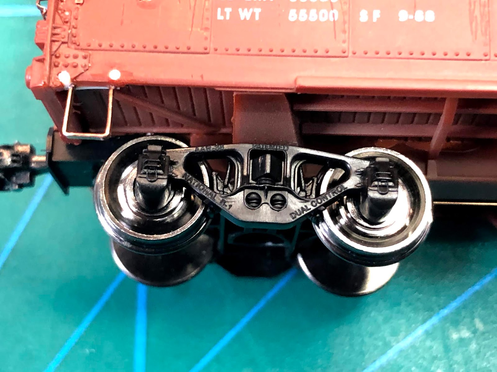
The Missouri Pacific rostered the largest number of 1932 ARA designed boxcars, 2500 in fact. These totals include the subsidiary companies I-GN (International Great Northern) and NOT&M (New Orleans, Texas & Mexico) cars. The cars ran without any major modifications throughout their lives. The one distinctive feature of the MP cars, is the choice of fixtures used on the Youngstown doors. They either came with Creco's Ball Bearing Fixtures or Railway Metal Product's Union Duplex Fixtures. For further information about these and all of the other 1932 ARA designed boxcars, I recommend Ted Culotta's excellent book "
The American Railway Association Standard Box Car of 1932".
 |
| Walter E. Frost, City of Vancouver Archives |
I decided to model one of the NOT&M cars, which had the Union Duplex Doors, 4-4 Square corner ends, wood running boards, Universal Brake housing and Murphy panel roof. The basis for this build is an Atlas 1932 ARA undecorated kit and parts kit (
MK-102.6) from my company National Scale Car. The decals were created by Ted Culotta and include MP, MI, and NOT&M reporting marks. I-GN cars did not have doors with the Union Duplex Fixtures and are not on the kit decal sheet. The kit includes resin doors and etched door tracks.
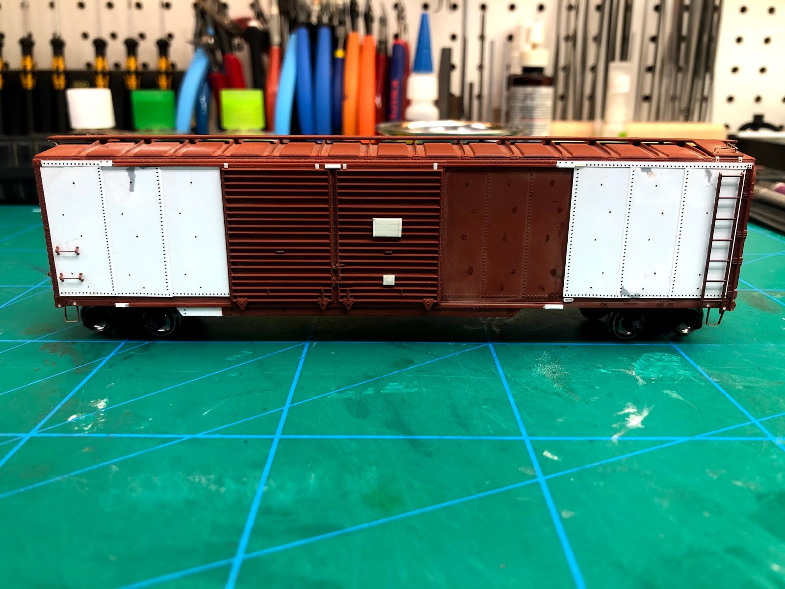
I started by reviewing the Atlas car body, to the prototype photo. Numerous small changes are needed, to build a more accurate representation of the car. A prototype photo of the NOT&M car is in Ted's Book, but the cars generally followed what is shown in the MI photo above (note - the MI car has 4-4 round corner ends). Changes are noted on the photo below.
Here is where I am at after and evening or two of work.
I will add rivet decals to the upper door track just before painting, that way I won't knock them off while working on the car.
The ends also need a few changes, as noted on the following photos.
The kit ladders are actually not too bad so I elected to keep them. The other features noted will be scratch built.
I'm not one for New Years Resolutions but I do like "to do lists". One of my favourite quotes is by Lee Iacocca - "The first step in accomplishing a goal, is to write it down". So with this in mind, here is what I want to get done in the next year.
Build the following Freight Cars.
MP 1932 ARA Car (Atlas and NSC mini Kit)
B&O M26D (Speedwitch Media Kit)
D&H Oneota built modified 1937 ARR (Yarmouth Model works)
Grand Trunk Shower Car (Scratch Build)
UP Flat Car (Proto 2000 kit with Speedwitch Media decals)
Grand Trunk Western War Emergency Gondola (Ends will be offered as a mini kit through NSC)
The following Pattern Work
B&O M55 parts for Mini Kits from NSC
3 Patterns on my bench (I will let Yarmouth Model Works make the announcement)
Single Sheathed Auto Car Pattern (TBD)
Duryea Under frames (4 different versions)
A diorama of Danville Junction.
Foam is cut, cork and ties are down. Need to lay track and construct a crossing diamond. I want to include the original Danville Junction crossing tower, but have yet to locate a useable photo of it. If you have one or know of a source I would appreciate some help. The original was torn down in 1963 from what I have learned.